IGCSE · 25 September 2026 · 6 min read
IGCSE Physics circuit questions: current, voltage and resistance worked through
Many circuit mistakes come from using the right equation with the wrong current or voltage. A battery supplies the whole circuit, but an individual component may have only part of the supply voltage across it or only part of the total current through it.
The useful skill is to label a circuit before calculating. These original IGCSE-level examples use ideal wires and a supply with negligible internal resistance. The resistors are treated as fixed resistances; a filament lamp can behave differently when its temperature changes. Use your own board's specification to check which network calculations are required.
Identify the connections, not the shape of the drawing
Two components are in series when they lie on the same unbranched path, so the same current passes through both. Parallel branches connect between the same two junctions and therefore have the same potential difference across them. A diagram can be stretched or rotated without changing those connections. Trace the wires rather than deciding from whether symbols appear side by side.
At a junction, total current entering equals total current leaving. Around a complete loop, the energy supplied per unit charge equals the energy transferred by that charge in the components. These conservation ideas explain why currents split at branches and why series voltage drops add to the supply voltage; they are not unrelated rules to memorise.
Worked example: a series voltage split
Connect a 4.0 Ω resistor and an 8.0 Ω resistor in series across 12 V. Their total resistance is 4.0 + 8.0 = 12 Ω, so the circuit current is I = 12 / 12 = 1.0 A. That current flows through both resistors. Their potential differences are V₁ = 1.0 × 4.0 = 4.0 V and V₂ = 1.0 × 8.0 = 8.0 V.
Check that 4.0 + 8.0 = 12 V. The higher resistance transfers more energy per coulomb because the same charge passes through each resistor while the larger resistance requires a larger potential difference for that current. Do not assign 12 V to both resistors: that would describe parallel connections and would contradict the stated series circuit.
Worked example: find branch currents before the total
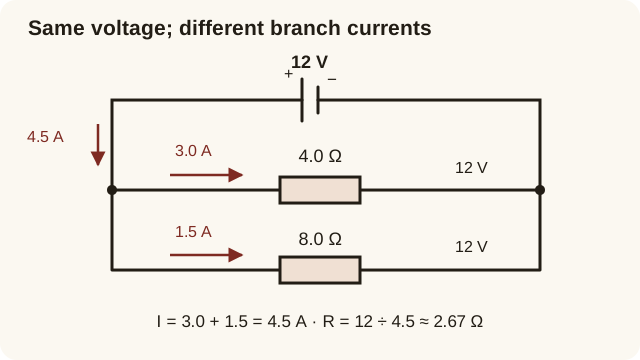
Connect the same 4.0 Ω and 8.0 Ω resistors in parallel across 12 V. Each branch has 12 V across it. The branch currents are I₁ = 12 / 4.0 = 3.0 A and I₂ = 12 / 8.0 = 1.5 A. The supply current is 3.0 + 1.5 = 4.5 A. The equivalent resistance is therefore R = V / I = 12 / 4.5 = 2.67 Ω, approximately.
The total resistance is lower than either branch resistance because adding a conducting path increases the current available at a fixed voltage. That does not mean every branch carries more current: with an ideal constant-voltage supply, the current in an unchanged branch remains V / R. It is the new branch that adds to the total supply current.
Connect meter placement to what a meter measures
An ammeter measures the current through a path, so place it in series with that path. An ideal ammeter has negligible resistance, avoiding a significant change in the current being measured. A voltmeter compares electrical potential at two points, so connect it across the component. An ideal voltmeter has very high resistance and takes negligible current.
A common mistake is drawing the voltmeter in the only conducting path. Its high resistance would make the circuit current very small. Another is connecting an ammeter directly across a supply: its low resistance can create a dangerously large current in a real circuit. For a paper question, redraw the intended measurement connections; for practical work, follow your teacher's equipment and safety instructions.
Predict a change before recalculating
If one resistor is added in series while the supply voltage stays fixed, total resistance increases and circuit current decreases. If a resistor is added as another parallel branch, total resistance decreases and total supply current increases. Always state which current you mean: branch current and total current can change differently.
For identical lamps, brightness can be compared through power transferred in each lamp, with a suitable model. In a fixed-resistance calculation, P = IV or P = I²R links the electrical quantities. Do not conclude that a lamp is brighter merely because it is drawn nearer the battery; steady current is not gradually consumed as it moves around a series circuit.
Independent practice: change a parallel branch
A 6.0 V ideal supply powers 3.0 Ω and 6.0 Ω resistors in parallel. Find each branch current and the total. Then remove the 6.0 Ω branch. Initially, the currents are 6.0 / 3.0 = 2.0 A and 6.0 / 6.0 = 1.0 A, giving 3.0 A total. After removal, the remaining 3.0 Ω resistor still has 6.0 V across it and carries 2.0 A; the supply current falls to 2.0 A.
The initial equivalent resistance is 6.0 / 3.0 = 2.0 Ω, and the final resistance is 3.0 Ω. This confirms the predicted direction of change. If your answer changed the remaining branch current despite the stated ideal supply, you probably treated the parallel resistors as a series voltage divider. Label the common junctions in your correction, then revisit the method later with different resistor values and no solution visible.
Questions, explained
Choose a question for a direct answer, then explore the explanation and supporting resources. Each answer has its own link to save or share.
Why is voltage the same across parallel resistors?
Parallel branches connect to the same two junctions, so the electrical potential difference between their endpoints is identical when connecting wires have negligible resistance. Their currents can differ because each resistance can differ. For example, across 12 V, a 4 Ω resistor carries 3 A and an 8 Ω resistor carries 1.5 A; both still have 12 V across them.
Is current used up as it passes through a resistor?
No. In a steady series circuit, the same rate of charge flow enters and leaves a resistor. Energy is transferred from the electrical system to the surroundings, but charge is not consumed by that transfer. At a junction, current divides between paths and recombines later; the sum of branch currents equals the total current.
When can I use the battery voltage in V = IR?
Use the battery's terminal voltage with the whole circuit's equivalent resistance and total current. You can also use it for a single component directly across that supply. For one resistor within a series branch, first find its own voltage or the current through the branch. Mixing the total supply voltage with one series resistor's resistance gives the wrong component current.