The key idea
The IGCSE hand-waving becomes two laws with names: Faraday's, which sets the size of the induced e.m.f., and Lenz's, which sets its direction — and turns out to be conservation of energy wearing a magnetic disguise.
Understand it · 01
Use the angle to the area normal
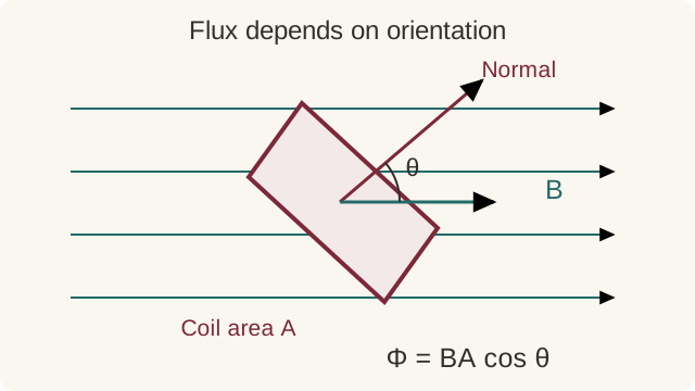
Magnetic flux through a flat area in a uniform field is Φ = BA cos θ, with θ measured between the field and the normal to the area. The normal is perpendicular to the plane of the loop. Flux is greatest when the field passes straight through the loop and zero when the field lies in its plane. Magnetic flux linkage is NΦ for N turns that each link the same flux.
Changing the field strength, the area within the field, or the orientation of a coil can change its flux linkage. A stationary coil can therefore have an induced emf if the field changes, and a moving coil can have no emf if its flux linkage stays constant. Merely saying that a coil is near a magnet is insufficient. Identify exactly what changes and how that affects the flux passing through the turns.
Understand it · 02
Separate magnitude from direction
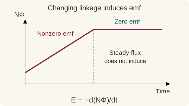
Faraday’s law states that induced emf is the negative rate of change of flux linkage. For an average over a time interval, use the change in NΦ divided by the elapsed time. A shorter change produces a greater average emf for the same total change in linkage. On a flux-linkage–time graph, emf is related to the gradient, not the height. A constant nonzero flux linkage therefore gives zero induced emf.
The negative sign expresses Lenz’s law: the induced effect opposes the change that caused it. If flux through a loop increases, the induced current produces a field that acts against that increase; if it decreases, the induced field tends to maintain it. An emf can exist around an open circuit, but a sustained induced current needs a conducting path. Mechanical work used to push a magnet into a closed coil supplies the transferred electrical energy.
Understand it · 03
Link the changing flux to useful devices
For a coil rotating uniformly in a uniform field, flux linkage changes sinusoidally. The induced emf is greatest when the flux linkage crosses zero most rapidly, and zero when linkage is at an extreme. Increasing turns, field strength, coil area or angular speed increases the peak emf in the ideal model. Mechanical energy must be supplied against the effects of the induced current when the generator delivers power to a load.
A transformer uses changing current in a primary coil to create changing magnetic flux linking a secondary coil. In the ideal model the voltage ratio equals the turns ratio and input power equals output power, so a higher output voltage accompanies a lower output current. A steady direct current cannot maintain the required changing flux after switching transients. Real transformers lose energy through winding resistance and core effects, so efficiency is below the ideal limit.
Key definitions
- Magnetic flux (Φ)
- The product of the flux density and the area at right angles to the field: Φ = BA. Units: webers (Wb).
- Flux linkage
- The product of the number of turns and the flux through the coil: NΦ.
- Faraday's law
- The induced e.m.f. is equal to the rate of change of magnetic flux linkage: E = −d(NΦ)/dt.
- Lenz's law
- The direction of the induced e.m.f. (and current) is such as to oppose the change producing it.
Equations, units & conditions
Magnetic flux
Φ = B A cos θ
Units: Wb
Uniform field; θ is the angle between the field and the area normal.
Faraday's law — average emf
Eavg = −Δ(NΦ) ÷ Δt
Units: V
The minus sign gives Lenz’s direction. Use the magnitude for a size-only question.
Worked examples, step by step
Example 1
A 500-turn coil of area 4.0 × 10⁻³ m² sits in a field of 0.20 T perpendicular to its plane. The field falls to zero in 0.10 s. Find the average induced e.m.f.
Follow the method
- Initial flux linkage = NΦ = 500 × 0.20 × 4.0 × 10⁻³ = 0.40 Wb-turns.
- E = Δ(NΦ) ÷ Δt = 0.40 ÷ 0.10.
E = 4.0 V
Practice questions with worked solutions
Try each question on paper before opening the solution. These are original academy questions; the suggested marks are a self-checking guide, not an official exam-board mark scheme. Difficulty labels describe this practice set, not predicted grades.
Build · 3 suggested marks
1. Average induced emf
Flux through each turn of a 150-turn coil changes from 2.0 × 10⁻⁴ Wb to 0.50 × 10⁻⁴ Wb in 0.030 s. Find the magnitude of the average induced emf.
Show solution and self-check: question 1
- Change in flux magnitude per turn = 1.50 × 10⁻⁴ Wb.
- |emf| = N|ΔΦ|/Δt = 150 × 1.50 × 10⁻⁴/0.030.
0.75 V.
Self-check · one mark per point
- Calculate the change in flux, not the final flux.
- Multiply by the number of turns.
- Divide by the time interval to obtain 0.75 V.
Build · 3 suggested marks
2. Ideal transformer
An ideal transformer has 800 primary turns and 200 secondary turns. The primary voltage is 240 V and the secondary delivers 3.0 A. Find the secondary voltage and primary current.
Show solution and self-check: question 2
- Vs/Vp = Ns/Np = 200/800, so Vs = 60 V.
- Output power = 60 × 3.0 = 180 W.
- Ideal input current = 180/240.
Secondary voltage 60 V; primary current 0.75 A.
Self-check · one mark per point
- Apply the turns-to-voltage ratio.
- Use conservation of power for the ideal transformer.
- Obtain 0.75 A for the primary current.
Common mistakes & how to avoid them
- Saying the e.m.f. is proportional to the flux. It is proportional to the RATE OF CHANGE of flux linkage — a huge steady flux induces nothing. The word 'rate' is the mark.
- Lenz's law answers without the energy argument: the induced current opposes the change, so work must be done against the opposition — that work is the source of the electrical energy. Without opposition, energy would appear from nowhere.
- Forgetting the N. For a coil, it is flux LINKAGE (NΦ) that matters; dropping the number of turns loses a factor of several hundred.
- Flux at an angle: Φ = BA cos θ, where θ is measured between B and the NORMAL to the coil — not the plane of the coil. Half of all flux errors are this angle.
Understand the why
Questions, explained
Start with the short answer, then follow the reasoning. Each explanation has a permanent link you can share with a classmate or return to when revising.
What is the difference between flux and flux linkage?
Magnetic flux measures the field passing through one surface, while flux linkage adds the flux linked by all turns of a coil. If each of N turns links the same flux Φ, the linkage is NΦ.
For a flat loop in a uniform field, Φ = BA cos θ with θ measured from the area normal. A coil with many turns can therefore produce a larger induced emf for the same per-turn flux change. Do not insert the turn count twice if a graph or measurement already gives flux linkage. The unit of flux is the weber; a turn is a count rather than a separate physical dimension. If different turns link different fluxes, add their individual contributions instead of assuming one identical Φ applies throughout the winding.
How does Lenz's law follow from conservation of energy?
Lenz’s law gives an induced effect that opposes the change causing it. This opposition requires an energy source to continue the change, allowing mechanical or other supplied energy to account for the electrical energy produced.
For a magnet approaching a closed coil, the induced current creates a magnetic effect opposing the increasing flux. Pushing the magnet requires work, and electrical energy can then be transferred to resistance or a load. If the induced effect reinforced the change without any compensating energy input, the process could amplify itself without an energy source. An open coil can still have an emf, but little current means a different mechanical opposition from the closed-circuit case. Describe what is increasing or decreasing rather than saying the induced field always opposes the original field.
Why does dropping a magnet through a copper tube slow it down?
A falling magnet changes the magnetic flux through conducting paths in a copper tube, inducing eddy currents. Their magnetic effects oppose the motion, transferring the magnet’s lost gravitational energy mainly into thermal energy in the tube.
Copper does not need to be ferromagnetic for this braking effect. Its conductivity allows closed current paths, and the relative motion produces the necessary changing flux. The forces depend on the speed, geometry and electrical resistance, so the magnet can approach a lower terminal speed when magnetic drag balances weight. Cutting a longitudinal slit interrupts some current paths and can reduce the braking. The effect does not require physical contact between the magnet and tube; it results from electromagnetic induction, with energy still conserved across the complete system.
How do I find induced emf from a flux-linkage graph?
Induced emf is the negative gradient of a flux-linkage–time graph. A large constant linkage gives zero emf, while a rapid change gives a large magnitude. Use a secant for average emf over an interval and a tangent for an instantaneous value.
The vertical axis determines whether a turn count is needed. If it shows flux per turn, multiply the gradient by N; if it already shows NΦ, do not. A rising and falling section give opposite emf signs for the same orientation convention. At a smooth maximum or minimum of linkage, the instantaneous gradient is zero, so the emf is zero there even though the flux magnitude may be greatest. For a piecewise linear graph, each straight segment corresponds to a constant average gradient and hence a constant emf on that interval.
A changing linkage
Flux linkage rises linearly from 0.10 Wb to 0.34 Wb in 0.040 s. Find average induced emf under the stated positive-flux convention.
- Δ(NΦ) = 0.34 − 0.10 = 0.24 Wb.
- Eavg = −Δ(NΦ)/Δt = −0.24/0.040.
−6.0 V; magnitude 6.0 V.
Why is generator emf zero when magnetic flux is maximum?
A rotating coil has zero induced emf when its flux linkage is momentarily at a maximum or minimum, because the rate of change is zero there. Maximum emf occurs when linkage crosses zero most rapidly.
For uniform rotation in a uniform field, flux linkage varies as a cosine and emf as the corresponding sine, so their peaks occur a quarter cycle apart. When the coil’s normal aligns with the field, flux magnitude is greatest but a small rotation initially changes it very little. When the field lies in the plane of the coil, flux passes through zero and changes rapidly. This is a rate-of-change argument, not a rule that more magnetic field always gives less emf: increasing field strength at fixed geometry and rotation speed increases the overall peak emf.
Which angle belongs in the magnetic flux formula?
In Φ = BA cos θ, θ is measured between the magnetic field and the normal to the loop’s plane. If the given angle is instead between the field and the plane, use the complementary angle or an equivalent sine expression.
The normal is an imaginary line perpendicular to the area. Maximum flux occurs when the field is normal to the loop, passing straight through it, while zero flux occurs when the field lies along the loop’s plane. These limiting cases help check the chosen trigonometric function. Use the area of one turn for Φ and multiply by the number of identical linked turns only when calculating linkage. The formula assumes a flat surface and a uniform field; for a nonuniform field, the local contributions across the surface must be considered.
Angle measured from the plane
A 0.020 m² loop is in a 0.30 T field making 30° with its plane. Find flux magnitude.
- The angle to the normal is 60°.
- Φ = BA cos 60° = 0.30 × 0.020 × 0.5.
3.0 × 10⁻³ Wb.
Your learning checklist
Use these goals to check your understanding. Requirements vary by specification, tier and exam year; the official references below define your full course.
- Define magnetic flux Φ = BA and flux linkage NΦ; the weber
- State and use Faraday's law: induced e.m.f. = rate of change of flux linkage
- State and use Lenz's law; relate it to conservation of energy
- Explain induction experiments: moving magnets, rotating coils, changing fields
Sources & how to cite these notes
Original explanations, illustrations and practice by Dr Desouky Physics Academy. Official specifications guide the course scope; questions and suggested marks on this page are our own revision material.
Reference this page
Dr Desouky Physics Academy. Edexcel IAL Physics: Electromagnetic induction. Updated 2026-09-25. https://www.drdesouky.com/revision/a-level-physics/electromagnetic-induction
Use the arrow beside an explanation heading to link straight to that section. Spotted a problem? Contact the academy with the topic and the step you want us to check.